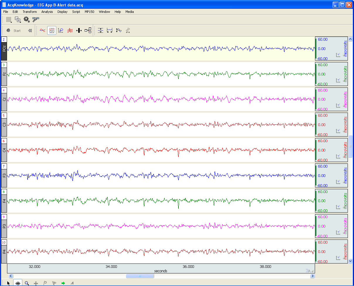
Forming Cooperative Learning Groups: The Challenge

By Howard Iver Thorsheim, Ph.D., St. Olaf College. Extensive research has repeatedly validated the value of cooperative learning. Yet, attempts to form cooperative learning groups too often failed to meet the expectations of both educators and students.

Photo © 2016 Knowledge Growers, Inc.

By Howard Iver Thorsheim, Ph.D., St. Olaf College

Howard Iver Thorsheim is Professor of Psychology and Neuroscience at St. Olaf College, Northfield, Minnesota, USA. In these blogs he offers his first-person insights into effective teaching techniques gleaned from a combination of scholarly research and over 40 years in the classroom.

Extensive research* has repeatedly validated the value of cooperative learning, and many educators desire to incorporate cooperative learning into their classrooms. Yet, my attempts to form cooperative learning groups too often failed to meet the expectations of both me and my students.

It took me many tries before I developed a simple process, which was stimulated by a question from a student. The process is an effective way to form cooperative learning groups for students to work together in doing psychophysiology (that’s a favorite name I use to describe teaching and learning psychophysiology in class and lab). The process is one that I have refined and used successfully ever since.

Psychophysiology content, research methods, and learning to use technology for measurement are my goals, as well as helping students learn take-away “soft” skills that will be useful to them in any setting, like how to work cooperatively with others.

But before they could cooperate, I needed to have students get into groups. My first tries to form groups disappointed me: I tried using the class list, taking the first three people in the list to make a group, and then the next three people and made them a group, and so on.

Another time I randomly picked groups of three and assigned them to groups.

Yet another time I thought that providing choice in choosing teammates would be a good reason for success, and asked students to form their own groups of three.

None of these methods generated the kind of “special spark” I was looking for.

I was about to decide that it did not make any difference how groups were formed, and that besides, forming groups just made for more work for them and for me. Then, I decided to ask my next semester students if they had any ideas about forming cooperative groups.

In Part 2 of this blog, I’ll share what I learned and how it worked.

* Johnson, D. W., Johnson, R. T.,  & Smith, K. A. (2014). Cooperative learning: Improving university instruction by basing practice on validated theory. Journal on Excellence in College Teaching, 25(3-4), 85-118. (Find an abstract of their article here). A quick way to get to that information is to download a copy of a 2013 draft version of the 2014 Johnson, Johnson & Smith article, available here.

Learn more about BIOPAC’s education solutions, including complete teaching systems for psychophysiology and the life sciences. BIOPAC also provides a wide range of research systems for recording, displaying, classifying, and analyzing psychophysiological measurements.

BIOPAC Systems, Inc. provides life science researchers and educators with data acquisition and analysis systems that inspire people and enable greater discovery about life. Visit us at www.biopac.com.

Professor Thorsheim is a licensed Psychologist, educator, and author. He has published or presented over 125 papers, journal articles, books, book chapters or monographs, and received a patent in 1985 as a co-inventor for an educational book design with interactive elements. His work has been funded by marquee foundations across the globe. His most recent work is Doing Psychophysiology: Getting Started, available from Knowledge Growers, Inc., available as an iBook download in 51 countries.

.
Dark Current Measurement as a Noise Management Tool

Noise in functional near infrared (FNIR) imaging data utilized for neurophysiological brain functioning research is a challenge to researchers, The use of dark current measurement in functional near infrared (fNIR) brain imaging can provide a valuable tool in identifying and managing certain type of noise in recordings.

By Davood Tashayyod, FNIR Devices

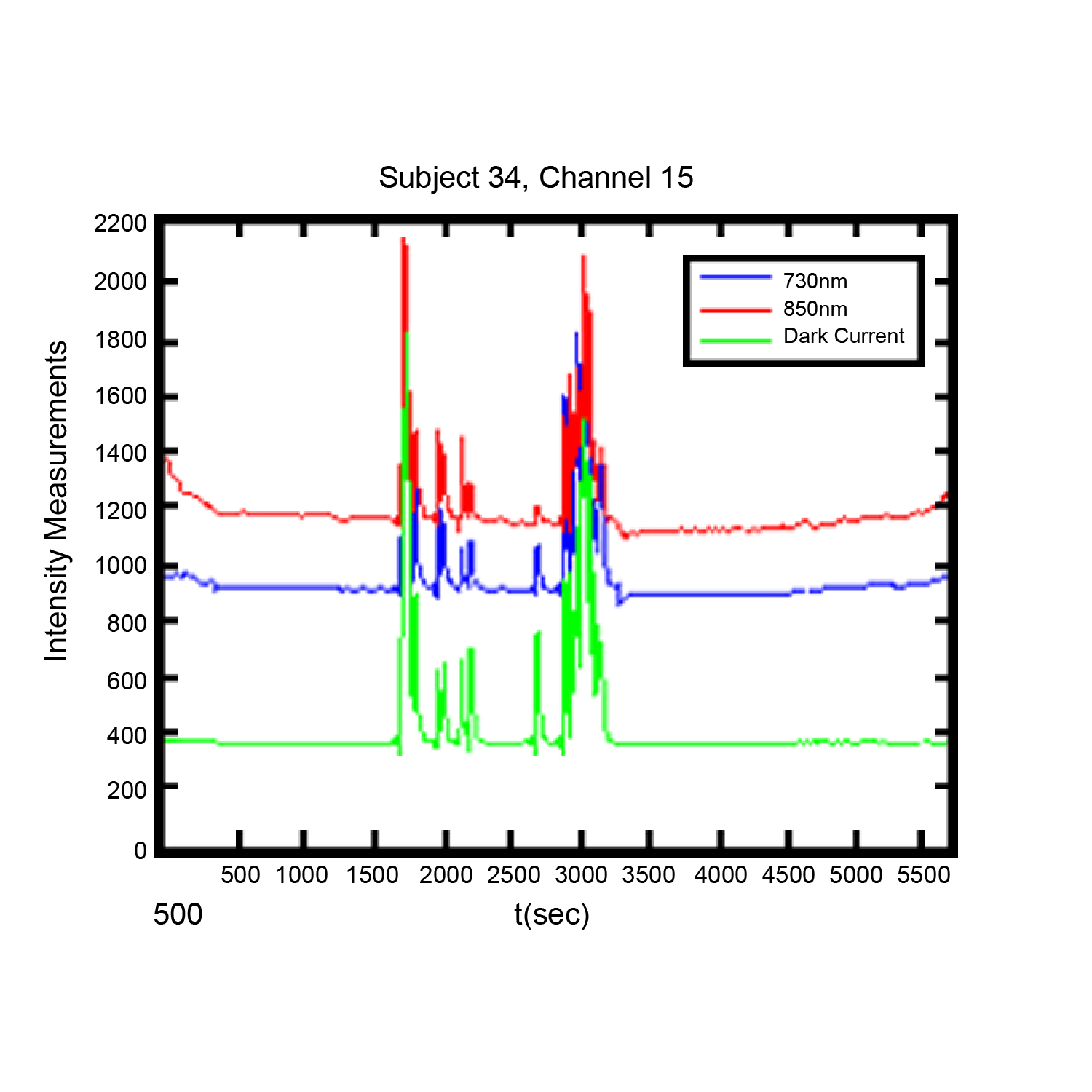
The use of dark current measurement in functional near infrared (fNIR) brain imaging (measurements taken not only when LED type light sources shine light at wavelengths 730 and 850 nm but also when they do not shine light (dark current condition)) can provide a valuable tool in identifying and managing certain types of noise in recordings.

Noise in functional near infrared (fNIR) imaging data utilized for neurophysiological brain functioning research is a challenge to researchers, in that excessive or unmanaged noise may pose a risk to the quality of gathered data and hence in the interpretation of the results. This noise arises from two general categories of sources, biological sources and non-biological sources. It should be noted that sources of noise are routinely present, so that noise cannot be eliminated but rather must be managed. Biological sources of noise include the respiratory and cardiac cycles and slow vasomotor oscillations. Non-biological sources of noise may include contamination from other external devices and noise induced by improper sensor application (light leakage, in the case of fNIR sensors), cable movements, or instruments or equipment used in the course of the experiment. These sources, independently or in combination, can mask the signals of interest.

Close attention to good laboratory practices, to include proper sensor placement, trial runs to establish baselines, and other techniques can help to reduce noise. Close attention to experiment protocols during the experiment can also be of assistance. However, it is in post-experiment data processing and analysis phases that the researcher has the greatest number of tools to manage noise. These tools include intuitive or visual analysis, filtering, and specialized analysis. Each method has strengths and weaknesses, but used in combination they offer a reliable method of managing noise and improving data quality.

Visual or intuitive analysis depends upon researcher experience and qualification, and some artifacts may be too small to be readily apparent. Filtering is useful, but in some range of measurements noisy data segments may be so great or may not contain any signal originated from the brain such as in the case when the sensor loses contact with the skin and captures data only from the ambient that it may not make sense to remove noise, rather such data segments should be identified and discarded.

Specialized analysis, such as dark current measurement, provide a very useful method for both identifying the noise not readily apparent to the naked eye and identifying data segments where filtering is likely to not be useful. A discussion of the use of dark current measurement can be found here.

For more information on optical braining imaging systems, visit BIOPAC’s fNIR page. BIOPAC also provides a wide range of tools for recording, displaying, classifying, and analyzing psychophysiological measurements—including EEG, ECG, EDA, PPG, and emotional states—visit BIOPAC’sapplications pages and view BIOPAC’s full line of physiology data acquisition and analysis systems, electrodes,amplifiers, and wearable, wireless transmitters and loggers.

BIOPAC Systems, Inc. provides life science researchers and educators with data acquisition and analysis systems that inspire people and enable greater discovery about life. Visit us at www.biopac.com.

Electrocardiography (ECG)

Electrocardiography (ECG) is a graph of electrical activity of the heart (cardiac) muscle as it changes over time. The basic principle of the ECG is that periodic waves of propagated electrical stimulation cause cardiac muscle to alternately contract and relax.

By Alan Macy, BIOPAC Systems, Inc

Electrocardiography (ECG) results in a graph of electrical activity of the heart (cardiac) muscle as it changes over time. Cardiac muscle contracts in response to electrical depolarization of the heart muscle cells. The ECG is the measured sum, over time, of this electrical activity as it is recorded from electrode connections.

Willem Einthoven’s contribution to ECG recording technology was the development of the string galvanometer that had improved sensitivity over the capillary electrometer. In 1908, Willem Einthoven published a description of a medically useful ECG recording system. This ECG system employed a specific lead connection method presently known as the Einthoven lead system. The Einthoven lead vectors are based on the assumption that the heart is located in a conductive volume. The Einthoven lead vectors are defined as:

Lead I: LA – RA

Lead II: LL – RA

Lead III: LL – LA

Where:

LA is Left Arm

LL is Left Leg

RA is Right Arm

The basic principle of the ECG is that periodic waves of propagated electrical stimulation cause cardiac muscle to alternately contract and relax. These electrical stimulation waves are transmitted from cardiac muscle cell to cell via gap junctions that connect between the cells. The electrical waves spread through the cardiac muscle cells because of cascaded changes in ions between intracellular and extracellular fluid. When the cardiac muscle cells are in a resting (polarized) state, the insides are negatively charged compared to the outsides. Cell membrane pumps maintain this electrically polarized state. Contraction of cardiac muscle is triggered by depolarization. Following depolarization, the cardiac muscle cells return to their resting charge. This process is called repolarization. These waves of depolarization and repolarization result in a changing electrical potential and can be detected by placing electrodes on the surface of the body.

The normal cardiac cycle begins with spontaneous depolarization of the sinoatrial (SA) node, a small volume of specialized tissue located in the right atrium. The SA node sets the rate of the heartbeat. The SA generated wave of electrical depolarization then spreads through the right atrium and across the inter-atrial septum into the left atrium causing the atria to contract. This contraction pushes blood into the ventricles. The atria are separated from the ventricles by a ring of non-conductive tissue. Accordingly, the only conductive path of electrical depolarization, from atria to ventricles, is through the atrioventricular (AV) node. The AV node is a cluster of cells in the center of the heart between the atria and ventricles. The AV node is a pathway that slows the electrical depolarization wave before it enters the ventricles. The wave of depolarization travels down the interventricular septum, through the His-Purkinje fiber network, to the left and right ventricles. The AV node delay gives the atria time to contract, before the ventricles do, to establish robust pumping action. In addition, with normal conduction, the two ventricles contract simultaneously to further maximize cardiac performance. After a volume of cardiac muscle cells depolarizes, the cells repolarize for the next cardiac cycle.

The net (average) path of electrical depolarization, through the heart, is known as the electrical axis. A fundamental ECG measurement principle is that when the wave of electrical depolarization travels toward a recording lead, this results in a positive voltage on that lead. When the wave travels away from a recording lead this results in a negative voltage on that lead. During repolarization, net wave activity towards or from a recording lead results in the opposite polarity as compared to depolarization.

The nature of the repolarization wave is different, from that of the depolarization wave, in that repolarization is not a propagating phenomenon. Cardiac muscle cell repolarization only occurs after the depolarization action potential duration, so cell repolarization does not depend on the repolarization of an adjoining cell. Assuming the action potential of all cells have equal duration, the repolarization wave would follow the same sequence as depolarization wave. However, in considering the entire extent of cardiac muscle, action potential duration is not identical between cells.

Meaning of ECG waves –

P wave: Depolarization of the right and left atria

QRS complex: Depolarization of the ventricles

T wave: Repolarization of ventricles

Meaning of ECG intervals –

PQ interval: Time period between start of atrial depolarization to start of ventricular depolarization

QRS duration: Time period of ventricular depolarization

QT interval: Time period between start of ventricular depolarization and end of ventricular repolarization

RR interval: Time period of complete cardiac cycle (inverse of heart rate).


For more information on BIOPAC’s wide range of tools for recording, displaying, and analyzing ECG measurements from human and animal subjects, visit BIOPAC’s electrocardiograpy, epages and view BIOPAC’s full line of electrodes, amplifiers, and wearable, wireless transmitters and loggers.

BIOPAC Systems, Inc. provides life science researchers and educators with data acquisition and analysis systems that inspire people and enable greater discovery about life. Visit us at www.biopac.com.

Electrodes for Physiological Recording

By Alan Macy, BIOPAC Systems, Inc.

In the context of human physiological recording, an electrode is a conductive probe which is used to sense the presence of biopotentials arising at points in the body. When biopotentials are generated in the body, they can be sensed using a differential voltage amplifier. When a biopotential source activates, electrons are moved within the volume of the source thus creating a voltage potential difference (positive to negative) across the volume of the source. Biopotential sources are continually changing in the body, so the associated differential voltage potentials change too.

Electrodes establish an equipotential area when attached to a location on or in the body. An equipotential area means that anywhere on the surface area of the electrode the potential (voltage) will be the same. This is because electrodes are substantially more conductive than the surrounding tissue. To record a biopotential signal, two electrodes are required. The pair of electrodes will measure the voltage which is impressed between the two equipotential areas created by the electrodes.

Biopotential recording electrodes are of two types, namely invasive and noninvasive. Invasive electrodes are designed to sense biopotentials inside the body, meaning they are inserted inside the body, past the skin boundary. Historically, invasive electrodes have been designed as needles or wires to better penetrate the skin. By controlling the conductive and insulating areas of the needle or wire, the electrode can be used to sense biopotentials originating at any depth in the body volume. If the invasive electrode is to be inserted into the body for a long time, then the electrode might take a different shape, such as a conductive disk which can be sutured into place.

Noninvasive electrodes are designed to sense biopotentials which manifest on the outside skin surface. These kinds of electrodes do not penetrate the skin surface layer. Because the body is a volume conductor, biopotentials originating anywhere in the body travel to the entire skin surface area. As an example, a polarized biopotential wave is generated by the heart during the course of each beat. This signal is easily detectable between any two locations on the body’s skin surface that are physically oriented to different sides of the heart.

In practice, it’s best to collect biopotential data as near to the biopotential generating site as possible for the best recording. This is because the body generates a large number of biopotential signals, sourced from a variety of excitable cells. Because the body is conductive, a myriad of these signals will superimpose at any body recording location. As the distance grows between a particular source and the differential recording location, the source signal attenuates. Sources, that are subject to a range of attenuation, will simply add to the desired signal being measured, as they are included in the volume conduction path defined by the differential biopotential recording.

When collecting biopotential data from surface electrodes, the contact area of the electrode has an impact on the frequency and amplitude components recorded in the biopotential. Because the body volume is relatively conductive, increased electrode surface area has a tendency to reduce biopotential amplitudes and suppress higher frequency components. This happens because multiple, and often uncorrelated, biopotential sources in the body can act in random opposition as the various biopotentials superimpose in the conductive body volume and then express on the skin surface. A biopotential averaging process takes place in the body tissue volume and an aspect of the averaged signal is reflected on the skin surface area. This biopotential signal averaging quality increases in scope as the size the measurement surface electrodes increases.

If a biopotential electrode is reduced in size and then inserted into the body near the location of interest, then measured signals will typically increase in amplitude and frequency components. These kinds of electrodes are called needle or wire electrodes and typically have an insulating needle shaft with a conductive tip. Despite certain benefits of needle electrodes, complications can arise when breaking the skin barrier and inserting foreign objects into a subject’s body. Needle electrodes can be difficult to use because they have smaller surface area than surface electrodes. Furthermore, smaller contact surface area always means that the electrode contact impedance is higher. Very high contact impedance, typically in excess of 1 Mohm, specifies the need for excellent lead shielding and specialized input amplifier characteristics.

Biopotential measurements from surface electrodes on the body have material harmonic content of less than 500 Hz. Nearly all of the signal power which can be collected from surface electrodes is between DC and 500 Hz. If the electrode is smaller, such as a conductive-tipped needle, and inserted through the skin surface to near the biopotential of interest, biopotential signal frequencies can exceed 10,000 Hz.

For more information on BIOPAC’s wide range of tools for recording, displaying, and analyzing biopotential measurements from human and animal subjects, visit BIOPAC’s electrocardiograpy, electromyography,  or electroencephalograpy pages and view BIOPAC’s full line of electrodes, amplifiers, and wearable, wireless transmitters and loggers.

BIOPAC Systems, Inc. provides life science researchers and educators with data acquisition and analysis systems that inspire people and enable greater discovery about life.  Visit us at www.biopac.com.

Electroencephalography (EEG) Pt. 2

Short-term Electroencephalography or EEG measurements are typically performed in synchrony with well-controlled, environmental, stimuli. Signal-averaging measurements, of this type, are known as Event Related Potentials (ERPs).

By Alan Macy, BIOPAC Systems, Inc.

This blog is a continuation of the previous discussion of Electroencephalography or EEG. Short-term Electroencephalography or EEG measurements are typically focused on the nature of cognition. These types of recordings are typically performed in synchrony with well-controlled, environmental, stimuli. Signal-averaging measurements, of this type, are known as Event Related Potentials (ERPs). There are a range of ERP signals, stretching between 50 ms to many seconds, with respect to the occurrence of the event. ERPs require signal averaging methods, to be observed, because their amplitude levels (0.2-2 uV) are usually lower than the ambient EEG signal level.

ERPs can be generated by a wide range of stimuli. The stimulus event can be targeted to any specific human sense or combination of senses (auditory, visual, olfactory, touch or taste). ERPs indicate the superimposed potentials of neuronal activity that synchronously generate when a subject processes sensory information. There are two general types of human subject ERPs. Early ERP wave components occur before 100 milliseconds after the stimulus. Late ERP components occur after 100ms after the stimulus. Early ERPs are known as exogenous potentials and late ERPs are known as endogenous potentials. Exogenous potentials depend on neuronal sensory structure responses that occur prior to cognition.  Endogenous potentials depend on cognitive responses to the sensory stimuli.

Slow Cortical Potentials (SCPs) are a class of ERPs that are characterized by slowly-moving, stimulus-related changes in the EEG signal. SCPs originate in cell concentrations in the top cortical layer of the brain. SCP waves (0.01-3 Hz) are EEG signals that occur before and after stimulus presentation. They encompass such pre-stimulus measures as Contingent Negative Variation (CNV) and Readiness Potential (RP).  The CNV is a slow-changing negative potential that happens between an initial warning and a “go” stimulus.  NV amplitude depends on the subject’s expectation of an imagined, forthcoming event. The RP is associated with the beginning of movement.  The RP precedes movement and is identified as a slow-changing negative potential that maximizes with movement onset. The RP is observed when signal averaging the EEG, from the motor cortex, synchronously with movement.

EEG can be useful to:

  • Monitor alertness and conscious states
  • Evaluate inhibitory control over behavior
  • Locate areas of neural damage
  • Establish levels of cognitive engagement
  • Investigate brain disorders, such as Alzheimer’s, epilepsy and seizures
  • Establish brain / computer interfaces
  • Monitor sleep

For more information on BIOPAC’s wide range of tools for recording, displaying, and analyzing EEG signals from human and animal subjects, including automated EEG analysis, seizure detection, evoked responses and many others, visit BIOPAC’s EEG Analysis page or view BIOPAC’s full line of electrodes, amplifiers, and wearable, wireless transmitters and loggers.

BIOPAC Systems, Inc. provides life science researchers and educators with data acquisition and analysis systems that inspire people and enable greater discovery about life.  Visit us at www.biopac.com.

Electroencephalography (EEG) Pt. 1

An EEG recording can be short or long-term. Shorter-term, signal-averaged, EEG measurements are typically used to evaluate precognitive and cognitive processes with respect to specific stimuli.

by Alan Macy, BIOPAC Systems, Inc.

EEG or Electroencephalography is the measurement of differences in electrical potential (voltage) between points on the scalp. These voltages differences are the result of ionic current flow within neurons, and glial cells, in the brain. The measured scalp voltages are primarily in the 200 nV-200 uV amplitude range, 0.01 Hz – 100 Hz frequency range, and are typically simultaneously recorded at multiple sites on the scalp. The EEG is usually collected using the 10-20 electrode montage. This arrangement of electrodes typically references left or right hemisphere electrodes to the left or right earlobe (or mastoid), respectively. However, a wide range of signal referencing methods are used depending on the situational requirements.

An EEG recording (knows as an electroencephalogram) can be short or long-term. Shorter-term, signal-averaged, EEG measurements are typically used to evaluate precognitive and cognitive processes with respect to specific stimuli. These EEG signals have relatively low amplitude levels, typically 200 nV – 2 uV, so signal averaging methods are required to discern these signals from background concurrent EEG sources. Longer-term, non-signal-averaged, EEG measurements are used to discern the subject’s, real-time, conscious state. Different and observable wave rhythms are evident during such recordings. Commonly observed rhythms include: Delta, Theta, Alpha, Beta and Gamma waves. These waves can be continuously recorded and are in the range of 2 uV – 200 uV.

Delta waves (0.5-4 Hz) are considered slow rhythms and tend to be the highest in amplitude. Delta waves are normally the dominant rhythm in infants. Delta waves are found in sleeping adults and consistent Delta is considered abnormal in conscious adults.  Delta waves are low-frequency EEG patterns that increase during sleep in the normal adult.  Although Delta waves are generally prominent during sleep, there are cases when Delta rhythms are recorded from awake individuals. Delta waves may increase during difficult mental activities requiring concentration and other continuous-attention tasks. Delta rhythms depend on activity of motivational systems, in the brain, and participate in the identification of prominent phenomena.  The presence and amplitude of Delta rhythms are highly variable within and between individuals.

Theta waves (4-8 Hz) are considered slow rhythms. Theta waves are normal in children up to 13 years old.  Theta waves are found in sleeping adults and consistent Theta is considered abnormal in conscious adults. Theta rhythms are low-frequency EEG patterns that increase during sleep in the normal adult. Although Theta rhythms are generally prominent during sleep, there are cases when theta rhythms are recorded from awake individuals.  Theta rhythms are involved in memory and emotional regulation. Theta waves will spike during emotional responses to frustrating events or situations.  Theta waves are associated with the inhibition of elicited responses, in that Theta activity has been found to temporarily increase when a person is actively trying to repress a behavioral response. The presence and amplitude of theta rhythms are highly variable within and between individuals.

Alpha waves (8-13 Hz) are considered moderate rhythms and usually seen in the occipital regions of the head and are higher in amplitude on the dominant side. Alpha waves appear when relaxing and closing the eyes. Alpha waves are suppressed when opening the eyes or coming to an alert state. Alpha waves are the primary rhythm observed in relaxed adults and are present during most of life after 13 years old. Each region of the brain has a characteristic Alpha rhythm amplitude and the largest Alpha waves are from the occipital and parietal regions of the cerebral cortex. Alpha rhythms correlate with inhibitory processes in the brain. Reduced Alpha wave occurrence and amplitude, in relation to Delta-Theta activity, is associated with reduced inhibitory control over behavior.

Beta waves (13-30 Hz) are considered fast rhythms. Beta waves are typically observed on both sides of the head and are most evident frontally (executive function). Beta waves may be substantially reduced in areas of cortical damage.  Beta waves are considered normal and are the dominant rhythm in subjects whose eyes are open or are otherwise attentive to external stimuli or exerting specific mental effort. Beta rhythms also occur during rapid eye movement (REM) sleep. In this situation, the typical Alpha rhythm is suppressed and supplanted by Beta waves. This replacement of Alpha rhythm is called desynchronization, or “Alpha block”, because it represents a change in the synchronized activity of neural systems in the brain. It is thought that Beta waves represents arousal of the cortex to a higher state of alertness and may also be associated with memory retrieval.

Gamma waves (30-100 Hz) are considered fast rhythms. Gamma waves are present during mixed sensory processing, such as perceptual tasks that combine hearing and seeing. Gamma waves are also evident during short-term memory matching of recognized sights, sounds or sensations. A reduction in Gamma wave activity might be associated with cognitive decline, especially when compared to Theta wave activity levels.

Long-term EEG signal characteristics are related to consciousness. As conscious activity increases, the dominant EEG rhythms shift to higher frequencies. When asleep, with the exception of REM, the dominant EEG rhythms move to lower frequencies.  In deep sleep, the EEG is characterized by low frequency Delta waves.

This blog is continued in Part 2.

For more information on BIOPAC’s wide range of tools for recording, displaying, and analyzing EEG signals from human and animal subjects, including automated EEG analysis, seizure detection, evoked responses and many others, visit BIOPAC’s EEG Analysis or view BIOPAC’s full line of electrodes, amplifiers, and wearable, wireless transmitters and loggers.

BIOPAC Systems, Inc. provides life science researchers and educators with data acquisition and analysis systems that inspire people and enable greater discovery about life.  Visit us at www.biopac.com.

CNAP Noninvasive Blood Pressure Technology – An Overview

The interaction of an easy-to-use finger sensor with unique control loops and algorithms as well as with NBP provides high accuracy of the BP signal – equivalent to invasive arterial line.

By Dr. Jürgen Fortin, CEO, CNSystems

Continuous noninvasive arterial blood pressure measurement (CNAP®) is the technique for measuring blood pressure (BP) that is, as the title describes, both continuous and noninvasive. CNAP combines the advantages of the following two clinical “gold standards:” it measures blood pressure (BP) continuously in real time like the invasive arterial catheter system (IBP) and it is noninvasive, like the standard upper arm sphygmomanometer (NBP).

The CNAP principle is the intelligent interaction and synergy of IP-protected features and functions based on the well-known Vascular Unloading Principle by Penaz (with significant improvement over the past 15 years) [1], on unique control algorithms (e.g. VERIFI) [2] and on calibration mechanisms, making it a reliable and accurate method with results comparable to the intra-arterial measurement.

Pulsating blood flow detected by infrared light sensors is kept constant by the counter pressure exerted on the artery through inflating or deflating the integrated cuff. The resulting pressure in the finger sensor corresponds to the real arterial pressure [1]. The pressure system is controlled by multiple digital feedback loops. The “VERIFI-algorithm” is used for high fidelity signal processing and artifact rejection. This is a superior method for filtering vasomotoric influences, in contrast to Standard methods based on Vascular Unloading Principle, which can show false BP shifts due to influence of vasomotoric tone.

In terms of calibration, CNAP is the only available technology calibrating to directly measured upper arm values, providing blood pressure variations in absolute values at heart-level. The interaction of finger sensor with NBP provides high accuracy of the BP signal – equivalent to invasive arterial line.

Use of CNAP provides researchers with several benefits, including: 

  •  NBP Cuff – Automated scaling to brachial pressure (gold standard) at start of measurement and user programmable
  • Double finger sensor – Quick and error-free application
  • Continuous waveform – Continuous tracing of hemodynamic changes without interruptions to recalibrate; beat-to-beat systolic, diastolic, mean BP values
  • Connectivity – Plug-and-play integration into all common data acquisition systems and patient monitors
  • Data storage and analysis – Unlimited data storage via USB interface. Data format (*.csv) for import into all common data analysis software packages (e.g. BIOPAC’s AcqKnowledge®, Matlab, MS Excel, SPSS, etc.)
  • Accuracy – Reliably equivalent to invasive blood pressure (IBP) [3], [4]

Notes:

[1]  Jan Penaz, Brno, Czech Republic 1973.

[2]  Fortin J et al.: Continuous non-invasive blood pressure monitoring using concentrically interlocking control loops. Comput in BiolMed 36 (2006) 941 – 957.

[3]  Jeleazcov C et. al. Precision and accuracy of a new device (CNAP) for continuous noninvasive arterial blood pressure monitoring: assessment during general anaesthesia. BJA. 2010; 105(3):264-272.

[4]Biais, M. et. al. Continuous non-invasive arterial pressure measurement: Evaluation of CNAP device during vascular surgery Ann Fr Anesthesia.

Studies documenting the CNAP device’s performance can be found below:

Arterial stiffness is higher in older adults with increased perceived fatigue and fatigability during walking

Does conscious intention to perform a motor act depend on slow cardiovascular rhythms?

The Effect of Mainstream Media on Body Image and Stress Reactivity in Latina Females

For more information on BIOPAC’s Noninvasive Blood Pressure monitoring and measurement and cardiology research solutions, to include CNAP noninvasive blood pressure systems, visit BIOPAC’s NIBP page or view BIOPAC’s NIBP amplifiers (MRI and small animal applications are also supported) and related equipment for a wide variety of research applications.

BIOPAC Systems, Inc. provides life science researchers and educators with data acquisition and analysis systems that inspire people and enable greater discovery about life.  Visit us at www.biopac.com.

error: Content is protected !!