
Understanding Stimulus Presentation Studies

Stimulus presentation studies are an important aspect of modern research that record and organize a participant’s reactions and physiological data to various inputs. These studies are commonly used in neuromarketing or psychophysiological experiments. First off, what is stimulus exactly? Put simply, a stimulus is a sensory input delivered to a participant with the purpose of eliciting a particular response. These stimuli can consist of images, words, lights, sounds, virtual reality, scent, or even mild electrical impulses.

The idea is to present varying types of stimulus to a participant at expected or unexpected intervals and record his/her response. For example, a collection of images might be presented (one at a time) ranging from pleasant (say an impressive vista) to neutral (say a street scene) to unpleasant (possibly a striking snake or other “fight or flight” image). Programmable stimulus systems (such as E-Prime or SuperLab) to present the stimuli, and can be used with a Chronos or M-Pod response keypad that the participant presses, each key representing a different response (e.g., pleasant image = press Key 1, unpleasant = press Key 2, etc.). A physiological signal commonly gathered from the participant is electrodermal activity (EDA), which measures the perspiration generated in a participant’s palms or fingertips. This “eccrine activity” has a strong correlation with emotional responses. For studies involving visual stimuli, a camera may be used to record the participant’s facial expressions. The expressions are simultaneously recorded and categorized using software such as FaceReader.

Stimulus experiments are generally set up using the hardware and software of the stimulus system and the resulting physiological data and stimulus markers recorded using a data acquisition system, such as BIOPAC’s MP160 with STP100C, MP36, or Smart Center Systems. These systems include AcqKnowledge or Biopac Student Lab life science software and the MP data acquisition units that interface with the stimulus hardware.

In practice, setting up stimulus studies is easier than it sounds on paper. The parameters and stimulus types are set up via drag-and-drop-interfaces in the E-Prime or SuperLab software, and the hardware interface set up using an I/O or USB connection between the stim hardware and the computer. The stimulus and BIOPAC data acquisition software can easily reside on the same computer, as can all stimulus and BIOPAC data acquisition hardware.

Stimulus studies can range from a simple setup, such as a participant responding to a sound for reaction time studies, to more randomized studies utilizing different types of stimulus delivered at varying pre-programmed intervals.

When the study is completed, data can be analyzed in AcqKnowledge software, and the various stimulus/responses organized automatically using AcqKnowledge’s automated Stim-Response Analysis routine.

For more information about conducting Stimulus studies using E-Prime, SuperLab, and AcqKnowledge software, we invite you to view the following free webinars and video tutorials:

Stimulus Presentation and Event Mark Up with E-Prime

Stimulus Presentation and Event Mark Up with SuperLab

AcqKnowledge Stim Synchronization and Analysis

Focus Areas – Automatically Create Using Define Between Events

BIOPAC offers a wide array of wired and wireless equipment that can be used in your research. To find more information on solutions for recording and analyzing signals such as ECG, heart rate, respiration and more using any platforms mentioned in this blog post, you can visit the individual application pages on the BIOPAC website.


Keeping Physiology Students Engaged

Keeping students engaged in the study of physiology can be a challenging exercise. Once the sole province of dusty textbooks and cumbersome lab manuals, the computer age ushered in quantum advances in the packaging of physiology curricula. Disadvantages were reflected in the cost of the systems, which often dictated that students crowd around a single computer, peering over shoulders with craned necks at confounding interfaces.

These early systems often left students feeling somewhat isolated because with only one student or instructor operating the computer, it was often difficult to engage all group members. Setting up the data collection was also a challenge and data quality itself was often poor. An unwelcome result was low student satisfaction and learning.

Gradually systems improved, becoming easier to use and more comprehensive. Current student physiology packages (such as Biopac Student Lab) divide various physiological disciplines into individual guided lessons (up to 65) and offer a high degree of interactive and multimedia content. Still, the challenge remains, how to keep students engaged and invested in the study of physiology? When considering a system, the following factors can help in this regard.

Choose a system that allows students to collect data on themselves. Engagement is higher when recording and analyzing one’s own data. Another key is to choose a system designed to offer all students a role. The student who isn’t the subject can be a recorder, director, or computer operator, and students can rotate to ensure everyone has a turn at being a subject. Everyone at every station has an integral role, rather than simply observing while an instructor operates complicated equipment. Simplicity of setup is also important. Systems such as Biopac Student Lab are compact and have standardized, modular “Simple Sensor” leads and transducers. The BSL systems come with all hardware, software, and support materials needed to begin collecting high-quality data within minutes.

The system should also support students’ ability to take their lessons home for further analysis. Biopac Student Lab can be augmented with a free downloadable analysis version of the software that can be used on any computer for analyzing data outside the lab. This enables students to remain more connected with their studies.

Lastly, interactive interfaces with clear onscreen instructions augmented by electronic and printed lab manual documentation are very helpful for beginning physiology students, and the system should be powerful enough to achieve clear, precise results while allowing for statistical comparisons be upper-level students.

This short list of key concepts encourages every student’s full participation, helps ensure all data is accurate, and allows students and instructors alike to obtain the most from the lab experience.

For more, click to watch a free BIOPAC webinar: Teaching Physiology: How to Engage Students in Lab Environments.

BIOPAC offers a wide array of wired and wireless equipment that can be used in your research. To find more information on solutions for recording and analyzing signals such as ECG, heart rate, respiration and more using any platforms mentioned in this blog post, you can visit the individual application pages on the BIOPAC website.

Data Acquisition Basics—Filtering

When setting up data acquisition parameters, one area of befuddlement often involves the use of filters. Which ones should I use, and how do I set them up? What are they really, and why do I need them? In a nutshell, filters are configurable controls for removing certain frequencies from a signal, while leaving others unaffected, and are  useful for removing noise and improving signal quality. Filters can be set up in the software as “online” (applied in real time during acquisition) or “offline” (applied post- acquisition). Some BIOPAC amplifiers, such as the 100C series, include a bank of filter switches relevant to the type of signal being acquired. As far as which filter to use, that is dependent on the type of physiological signal being acquired and BIOPAC amplifiers and software presets will help steer you toward the correct type of filter to use. Subsequent blog entries will delve more into specifics about which types are appropriate for which signals.

As in our earlier blog about frequencies, we’ll again be using the “cars” analogy to bring filtering concepts  into sharper focus. Say we want to look only at cars on a freeway that are traveling at or above the speed limit. To effectively do this, we’ll need to find a way to remove the slower vehicles from view. To isolate the “fastest” cars, we would apply a “High Pass” filter. By “High Pass,” we mean this filter eliminates all frequencies that fall below a specified cutoff point, and allows the higher frequencies to “pass through,” or remain present in the signal. Using the “cars/freeway” analogy, setting a High Pass filter to target cars traveling at 60 mph would eliminate all cars traveling at or below 60 mph and leave all faster cars unaffected.

Conversely, we can apply a “Low Pass” filter, which would eliminate all cars traveling faster than a specified speed and leave only the slower cars intact. Another “combination” filter that can be applied is a “Band Pass” filter, which eliminates the fastest and slowest moving “cars” and retains all cars that are traveling at a specified speed. Additional common filters are:

Band Stop isolates and removes a specific frequency or frequencies (all cars traveling at one particular speed, or range of speed, leaving all the others). This filter is most commonly used to eliminate 50 Hz or 60 Hz electrical noise frequencies from a signal.

Comb Band Stop is another powerful filter commonly used for removing electrical noise. The Comb Band Stop filter removes not only the 50 Hz or 60 Hz frequency, but also all overharmonics, or “echoes” of that frequency. For example, if you are in an area of the world that uses a 50 Hz line frequency, the Comb Band Stop filter will eliminate from the signal the 50 Hz frequency, plus 100 Hz, 150 Hz, 200 Hz, etc. If you live in the U.S. or other part of the world that uses a 60 Hz line frequency, this filter will remove 60 Hz, 120 Hz, 180 Hz, 240 Hz, etc. (A better analogy for this type of filter might be musical notes and their octaves rather than cars traveling at speed.)

All filters discussed above are supported in BIOPAC AcqKnowledge and BSL 4 software, as well 100C series  amplifiers, and can greatly enhance signal and data quality.

For further reading on filters, please see the following resources:

www.biopac.com/knowledge-base/high-pass-filters/

www.biopac.com/knowledge-base/band-pass-and-band-stop-filters/

For more information, please view our Fundamentals of Physiological Data Recording.


BIOPAC offers a wide array of wired and wireless equipment that can be used in your research. To find more information on solutions for recording and analyzing signals such as ECG, heart rate, respiration and more using any platforms mentioned in this blog post, you can visit the individual application pages on the BIOPAC website.

Data Acquisition Basics—Understanding Gain Settings

BIOPAC amplifiers used with the MP160 Data Acquisition System are equipped with configurable settings designed for optimizing the physiological signal being acquired, one of which is the gain setting. What is gain? Put simply, gain refers to the amplifier’s ability to adjust the power or amplitude of an incoming signal. If an incoming signal is very strong, and the gain level on the amplifier is set too high, the signal may appear onscreen as “clipped,” resulting in loss of data. This can happen when the strength of the signal exceeds the maximum input voltage range of -10 volts to +10 volts supported by the MP160 Data Acquisition System. (Think trying to fit 20 lbs of oranges into a 10 lb bag.)

This condition, also known as “railing,” means the amplifier gain level needs to be reduced in order for the signal to fall within the maximum 20 volt peak-to-peak range. Conversely, if an incoming signal is weak or of low amplitude, the gain level will need to be increased, lest the signal appear too small onscreen for proper analysis. (Akin to trying to fill up a 10 lb bag with one or two oranges.)

A good rule of thumb for setting proper gain levels is to remember that a lower amplitude signal requires a higher gain setting, while a higher amplitude signal can tolerate a lower gain setting.

BIOPAC 100C Series amplifiers generally have four gain settings (for example, 500, 1000, 2000 and 5000, in the case of the ECG100C amplifier). A gain setting of 5000 would result in a signal amplitude 10x greater than the same signal set to a gain of 500. Although the gain settings on BIOPAC 100C amplifiers cover a wide range, the included ranges are tailored for the signal the amplifier is designed for. This means even if the gain is not optimally set, the signal should still be within an acceptable range.

AcqKnowledge software also automatically scales the incoming signal so that it fits within the graph channel, but for the highest data quality possible, attention should be paid to the gain setting of the amplifier. The good news is that AcqKnowledge software Module Setup walks you through proper configuration of amplifiers and transducers, thereby minimizing error and maximizing data quality.

For more information, view Fundamentals of Physiological Data Recording.


BIOPAC offers a wide array of wired and wireless equipment that can be used in your research. To find more information on solutions for recording and analyzing signals such as ECG, heart rate, respiration and more using any platforms mentioned in this blog post, you can visit the individual application pages on the BIOPAC website.

Data Acquisition Basics—Using Frequency to Determine the Correct Sample Rate

The characteristics of a particular body signal are dictated by its amplitude and frequency. The frequency of a signal can help determine the ideal rate at which to sample a particular signal, thus ensuring the resulting waveform is of the highest quality. Basically, the higher the frequency of a signal, the faster the sample rate that should be used. As an analogy – if we liken the various signals to a freeway and assume all cars are traveling in the same direction, but at different speeds, we can then determine the signal’s frequency band by looking at the slowest cars and the fastest cars. For comparison, a “slow car” would be an electrogastrogram (EGG) signal (0-1 Hz) and a “fast car” would be an electromyogram (EMG) signal (10-2000 Hz). In order to acquire the information correctly, we need to ensure the sample rate is set high enough to sweep up in our dragnet the fastest cars along with the slower cars. In the case of the EMG signal, if the sample rate is set to only 100 Hz, many of the faster “cars” would not be captured, and the definition of the upper frequency ranges would be lost in the resulting waveform. Conversely, 100 Hz would be more than sufficient to capture all of the “cars” on the EGG signal freeway. (Other frequency range examples for particular signals are: ECG = .05-100 Hz, EEG = 1-100 Hz, EOG 01.-100 Hz.) The good news is that BIOPAC sets the acquisition sample rate to a default of 2000 Hz in our  MP160 or MP36 systems for AcqKnowledge or Biopac Student Lab software, more than sufficient for most applications. That said, it’s good practice to determine the maximum frequency response of a particular signal and multiply that maximum by four times to arrive at the sample rate that will capture all the cars moving down the freeway.


BIOPAC offers a wide array of wired and wireless equipment that can be used in your research. To find more information on solutions for recording and analyzing signals such as ECG, heart rate, respiration and more using any platforms mentioned in this blog post, you can visit the individual application pages on the BIOPAC website.

Data Acquisition Basics: Your Body as a Battery—How Are Physiological Signals Recorded?

During the process of physiological data acquisition, the human body behaves much like a battery. Electricity flows from parts of the body that are negatively charged to parts of the body that are positively charged, and this occurs constantly throughout all living tissue.

Since each physiological signal has a distinctive electrical signature, we can place electrodes at the appropriate points on the body and accurately record the electrical activity of the desired signal. Modern data acquisition systems (such as the MP160 or MP36 systems) convert these analog signals into digital waveforms that can be displayed onscreen via life science software such as AcqKnowledge or Biopac Student Lab.

When acquiring physiological data, it’s important to understand the distinction between biopotential and transducer signals. Biopotential signals are electrical signals acquired directly from the body via electrodes, as previously referenced in the “human battery” analogy. Examples of biopotential signals are heartbeat (ECG), brain activity (EEG), muscle activity (EMG), eye movement (EOG),  and gastric system (EGG). Transducer signals differ from biopotential signals in that they are reliant on force, movement, or some other proportionate change, rather than electricity from the body. To measure these, the transducer itself provides a voltage signal which enables it to measure activity such as respiration/airflow, blood pressure, temperature, and grip strength. In all cases, the voltage signal produced by the transducer increases proportionately with the force, movement, or temperature exerted upon it. This affects the contour and appearance of the onscreen waveform.

Whether recording biopotential or transducer signals, both offer a glimpse into the varied and complex workings of the human body.


BIOPAC offers a wide array of wired and wireless equipment that can be used in your research. To find more information on solutions for recording and analyzing signals such as ECG, heart rate, respiration and more using any platforms mentioned in this blog post, you can visit the individual application pages on the BIOPAC website.
 

Data Acquisition Basics: What is an A/D Converter?

Analog : Data represented by continuously variable physical quantities, i.e. moving clock hands.

Digital: Data composed of bytes of information sampled at regular intervals.

Data acquisition for life science research and education has come a long way since the heyday of chart recorders and oscilloscopes. Chart recorders, while accurately rendering body signals using an ink stylus on long rolls of paper, lack the flexibility for closely analyzing or interacting with data. Oscilloscopes also pose similar limitations. The field of physiology study received a major assist with the advent of A/D (A-to-D) converters, which include industry-leading BIOPAC MP160, MP36/36R, or Smart Center Systems.
So what is an A/D converter? A/D converters are devices for converting analog signals to a digital format.

This principle can be applied to any type of analog information, such as recorded music or video, and lends itself especially well to conversion of physiological signals. The incoming analog signal (such as an ECG heartbeat) is “digitized,” which allows the signal to be accurately displayed on a computer monitor. During this process, the analog signal is “sliced” into samples per second (or Hz) by the A/D converter. The speed at which the signal slices are acquired is referred to as the sampling rate.

A good illustration of how a sampling rate works is to liken it to a dot-to-dot drawing, each dot appearing at regular intervals and tracing the amplitude and time outline of the incoming analog signal. The higher the sampling rate, the higher the concentration of dots, and the higher the resolution (quality) of the signal. The combined dots, or bytes, of digitized information are displayed onscreen as seamlessly precise waveforms that can be started, stopped, magnified, reduced, edited, autoscaled, transformed, or run through powerful automated analysis routines using BIOPAC AcqKnowledge Research Software.

A good acquisition sampling rate for most physiological data is 2000 samples/second, although certain body signals (such as lung volume measurements) require only 20 samples/second, while auditory studies benefit from a sampling rate as high as 20,000 samples/sec. The BIOPAC MP160 16-Channel Data Acquisition Unit supports sampling rates ranging from 0.1 samples/second to 200,000 samples/second. Try doing that with an analog chart recorder!


BIOPAC offers a wide array of wired and wireless equipment that can be used in your research. To find more information on solutions for recording and analyzing signals such as ECG, heart rate, respiration and more using any platforms mentioned in this blog post, you can visit the individual application pages on the BIOPAC website.

Wired or Wireless Data Acquisition Systems—How to Decide?

Data acquisition hardware and software packages have undergone rapid progress over the past several years. Cumbersome systems difficult to set up and operate have been superseded by compact modular arrays offering unprecedented convenience, power, and functionality. Researchers and educators in the field of data collection have never had it so good. One of the most oft-asked questions from current prospective end-users is which type of system will best serve my needs?

Wired systems have long been the bedrock of labs around the world. Components fit on a desk and connect to a laptop or desktop computer. The data acquisition unit (such as BIOPAC’s MP160) is combined with a scalable array of modular amplifiers, or in the case of BIOPAC’s MP36 or MP45, powerful functionality is built into an even more compact package. Wired systems generally offer a wider range of features, such as stimulation, MRI signals, gas analysis, laser Doppler flowmetry, pulse oximetry, variable rate sampling up to 400 kHz, more channels (including digital and calculation channels), and online signal averaging. Access to third-party hardware and special licensed features are more readily supported. In wired systems, the subject is tethered to the equipment via cabled transducers and/or electrodes, so if mobility isn’t an overriding concern, a wired system will prove to be a robust platform offering the fullest range of available data collection and analysis tools.

Despite the enhanced functionality offered by wired systems, many researchers and educators have embraced lightweight wireless systems (such as BIOPAC’s BioNomadix, BioNomadix Smart Center or BioNomadix Logger). Wireless systems offer the flexibility of allowing untethered subjects to roam freely, and are excellent for exercise studies or other protocols requiring unrestricted movement. All major physiological signals are supported, and data quality is equal to that of wired systems. Although sampling rates are limited to 2 kHz, this is generally more than sufficient for most physiological studies. The advantage of a wireless system is apparent when fast, accurate results from single or multiple ambulatory subjects are of paramount importance. The BioNomadix Logger even enables subjects to conduct lengthy protocols virtually unlimited distances from the lab, after which the data is downloaded to the computer, enabling researchers to analyze accurate physiological data acquired over time and distance. Certain advanced functionalities available in wired systems aren’t supported in wireless systems, so your lab’s necessity for these must also be carefully considered.

The bottom line is, if your lab requires the full range of available biometric signals in conjunction with advanced functionalities—and subject mobility is not a factor—wired systems are recommended. If compactness, mobility, portability, and access to all major life science signals are deciding factors, then your lab would be well-served by a wireless system.
When your experiment needs flexibility, portability or fast and easy setup, then the wireless Smart Center is the right choice.

Learn about BIOPAC’s newest wireless recording system in “Get Better Physiology Data—BioNomadix Smart Center.”

request article


BIOPAC offers a wide array of wired and wireless equipment that can be used in your research. To find more information on solutions for recording and analyzing signals such as ECG, heart rate, respiration and more using any platforms mentioned in this blog post, you can visit the individual application pages on the BIOPAC website.

Origins of Electrophysiology

Physiology and electricity share a common historical journey. In the mid 1700’s, the Austrian writer/philosopher J. Sulzer noted that when two metal discs were placed on his tongue—one copper and one zinc—the combined metals yielded an odd sensation and taste. He expansively described the copper-zinc taste as “green vitriol.” Although Sulzer did not comprehend the forces behind his observation, he was experiencing was the literal “taste” of electricity generated by the interaction of these dissimilar metals.

Electrical activity generated by the combination of dissimilar metals was further explored by the Italian physician and botanist Luigi Galvani (1737-1798). While poking the leg muscles of a freshly dissected frog with two probes of copper and steel, Galvani was startled when the frog’s leg suddenly twitched. What had happened? The frog was clearly dead. After subsequent frog experiments, some ambitiously involving the use of a metal wire exposed to lightning, Galvani began to refer to this ephemeral twitching activity as “animal electricity.” In 1781, he published his widely-read “Commentarius,” which laid the foundations for modern electrophysiology and neuroscience. In the decades following Galvani’s initial discoveries, this notion of animal electricity as the “spark of life” became the subject of spirited debate, and even found its way into Mary Shelley’s 1818 novel “Frankenstein” as the reanimating force for the title character’s  undead creation.

In 1799, Italian physicist and chemist Count Alessandro Volta (1745-1827), advanced Galvani’s discoveries into the first practical method of generating electricity. Volta rejected Galvani’s “spark of life” notion, and theorized that the “twitching” frog leg activity was not “animal electricity” but the result of an interaction between the frog’s leg and the metals. Volta further realized that the frog’s leg served as both a conductor of electricity (what we would now call an electrolyte) and as a detector of electricity. Using an electric eel as an natural example, he constructed alternating discs of zinc and copper with brine-soaked pieces of cardboard between the metals, which produced an electrical current. This became known as “Volta’s pile” and was the first “wet cell battery” that yielded a reliable, steady current of electricity.

Volta’s doctrine prevailed over Galvani’s until the 1820s, when Leopoldo Nobili used the newly invented “galvanometer” (a compass-like device for detecting electrical activity) to measure the current flowing through a frog’s leg muscle. This gave rise to a host of ghoulish experiments involving half-dismembered animals and severed human cadaver parts. It wasn’t until the 1840’s that researchers Carlo Mateucci and Emil du Bois-Reymond discovered that galvanic measurements of living muscle tissues could be steadily and reliably measured. Du Bois-Reymond pioneered research indicating that living tissue, such as muscle, was composed of “electric molecules,” and the measured electrical activity was the result of this native “electric molecule” behavior.

We now know that these are sodium, potassium, and other ions responsible for maintaining the “membrane potentials” in excitable cells, whether it’s a flexing muscle or a beating heart. Furthermore, these various measurements have unique electrical signatures that can be displayed as waveforms for muscle activity (EMG), heart activity (ECG) or a wide array of other body “signals.” Ultimately, electricity is a fundamental property of living organisms, the understanding of which was arrived at over a century of trial and error.

Watch Beauty and the Origins of Electrophysiology – TEDx talk by BIOPAC founder Alan Macy to learn more now!

BIOPAC offers a variety of industry-leading hardware and software solutions for conducting Electrophysiology* studies. For more information about recording and analyzing body signals using the MP160 and other platforms, please visit the individual application pages on the BIOPAC website. 
*Electrophysiology: the science and branch of physiology that pertains to the flow of ions (ion current) in biological tissues

Fundamentals for Recording Great Heart Rate Data: Subject Preparation

Electrocardiography (ECG) or EKG is one of the most commonly recorded signals as it can be used for a wide variety of heart related analysis. Acquiring good, clean data from subjects can prove difficult though. Everything from electrode options to hardware settings can influence ECG signal quality over research. The following guidelines provide a baseline for ECG recording setups to ensure accurate and quality data from participants.

The most common question when recording ECG data is where to place electrodes on the subject. Certain aspects of your research will help inform exactly where to place electrodes. The most important question to answer is what tasks are your participants performing.

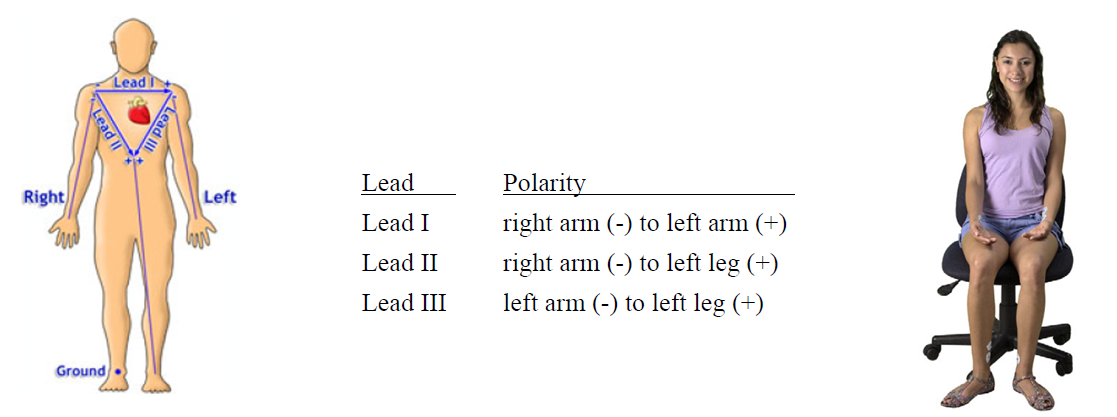
For most studies, the ECG placement can be placed by following Einthoven’s Triangle. This incorporates 3 leads; one running along the top of the chest, one running from right should toward left leg, and one running from left shoulder toward right leg. Place electrodes on the clavicle, wrists, or ankles. Note that if participants are moving around, placing on the wrists and ankles can prove difficult so place them instead on the chest area.

Always make sure to prepare your subject before placing electrodes on them. Abrade the skin before placement especially if placing on the wrists or ankles. Double check that the electrode is fresh and apply gel to the electrode for optimal adhesion. About 5-10 minutes after placement, use an impedance checker to check the electrode signal quality. These simple steps can make the difference between clean and noisy data.

If participants have been prepared correctly and the hardware is dialed in, the ECG waveform should resemble the classic ECG example. There are three primary elements to the electrical signal coming from the heart: P-wave, R-wave, and T-wave. Most lead configurations will resemble this waveform example.

EKG PQRST
ECG Waveform

These simple, but key guidelines will help ensure that ECG signals recorded from subjects are clean and high quality. Attach electrodes at the right parts of the body given the tasks that the participants will perform. Always make sure electrode sites are clean and that the electrodes are fresh. For more information and further instructions on recording ECG, visit the BIOPAC ECG applications page, ECG video tutorials, or view our ECG webinars.

BIOPAC offers a variety of wired and wireless equipment that can be used in ECG studies. To find more information on solutions for recording and analyzing signals such as ECG, heart rate, and respiration using the MP160 and other platforms, you can visit the individual application pages on the BIOPAC website. 

error: Content is protected !!